CLI Application
The CLI trainer application allows you to train CAD targets via a terminal application.
Train CAD
-
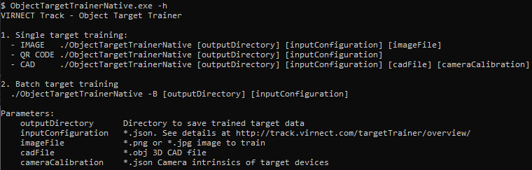
Starting the trainer application with no argument, or -h, or -help displays usage instructions.
-
To run CAD training you need to set the
- output directory,
- input configuration (e.g. defaultCADTargetTrainingConfig.json),
- CAD file,
- camera calibration
Detail Camera Calibration
The target data files must be generated with the camera intrinsics of the device used for tracking. Follow the instructions on Camera Calibration to generate a suitable calibration file.
Limitation: CAD Target Tracking currently only supports 640 x 480 input resolution (landscape mode).
Train targets for each camera (different FOV / different focal length) used for tracking.
Detail Input Configuration
The input configuration JSON file must contain the following:
defaultCADTargetTrainingConfig.json
{
  "Config.Target.Type": "CAD",
  "Config.Target.Name": "targetname",
  "CAD.UprightVector": [ 0.0, 1.0, 0.0 ],
  "CAD.Detection.DistanceRange": [ 0.3, 0.6 ],
  "CAD.Detection.NumTrainingViews": 1000,
  "CAD.Detection.ElevationAngleRange": [10.0, 70.0],
  "CAD.Model.DiscreteSymmetries": [0, 0, 0],
  "CAD.Model.ContinuousSymmetries": ""
}
Configuration parameter explanation:
Config.Target.Type
Always use "CAD" for CAD Training.
Config.Target.Name
The name of the Target. Allowed characters: 'a-z' 'A-Z' '0-9' '_'.
CAD.UprightVector
A vector that defines the upright axis of the object. By default, the upright axis is defined as the Y-axis of the model, therefore [0.0, 1.0, 0.0].
CAD.Detection.DistanceRange
Defines the detectable distance in meters. Large ranges can lead to less stable detection.
CAD.Detection.NumTrainingViews
Defines the number of viewpoints for training. A higher number of viewpoints increases the detection quality. A lower number of viewpoints increases runtime performance.
CAD.Detection.ElevationAngleRange
The minimum and maximum elevation angle in degrees from which the object should be detectable.
| Angle | Description |
|---|---|
| 90° | Top-down view |
| 0° | Horizontal view |
| -90° | Bottom-up view |
Depending on the possible orientation of the target in the environment consider restricting the elevation angles to improve the detection quality.
CAD.Model.DiscreteSymmetries
Defines for each axis (X, Y, Z) a single rotation, in degree, representing a discrete rotational symmetry.
[0, 180, 0] describes that the object is symmetric to 180 degree rotations on the Y-axis.
CAD.Model.ContinuousSymmetries
Defines one or multiple continuous symmetry axis. As an example, assign Y for an upright standing Cone.
Info
Batch training of CAD targets is not possible.